|
Antenna Primer Part II:
Copyright
by
Clem Small KR6A
In
this installment, we continue with our Antenna
Primer series by defining and discussing some terms which are useful in dealing
with antennas. We also build another antenna.
Antenna
Gain and Response Patterns
Antennas
differ in their sensitivity or response to signals which they receive. A more
sensitive antenna is said to have more gain because it responds to signals
which it intercepts by producing a greater signal output for the receiver than
will an antenna with lower gain.
Nondirectional
antennas have equal gain to signals coming to them from all directions.
Directional antennas are more responsive to signals coming from certain
directions than from other directions: thus their gain is different in different
directions.
A
figure showing an antennas gain or responsiveness to signals from different
directions or vertical angles can be called its reception pattern (Figs.
1A and 1B). The performance of an
antenna in transmitting the power which it receives from a transmitter and
sending it in different directions gives a radiation pattern identical in
shape to its reception pattern. Because reception and radiation patterns are
identical, either one may be referred to as the radiation pattern.
However, to avoid confusion they can be referred to individually by separate
terms, or collectively as the radiation and reception (R&R) pattern.
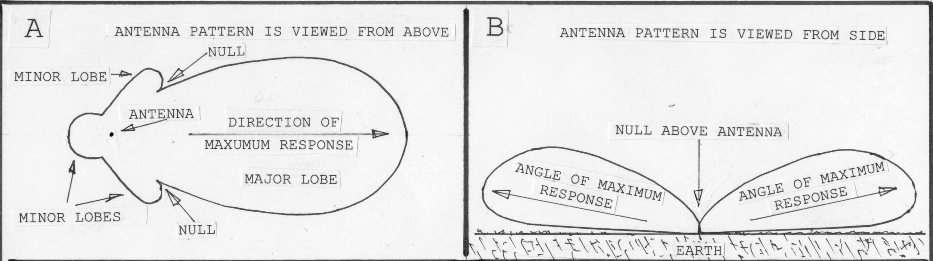
The
portion of the pattern showing directions of maximum response (or gain) are
called lobes, (1A & 1B), and those showing minimum response are called
nulls (fig. 1A & 1B). An antennas gain is usually specified as the
gain of its most responsive lobe.
Although
a minimum amount of gain is necessary for satisfactory reception or
transmission, it is not necessarily true that more gain is always better. For
example, a directive pattern may allow us to reduce received noise from certain
directions and hear weak signals from other directions better than with an
antenna of higher gain and a different pattern. Appropriate patterns can also
help avoid radiating interference to locations not involved in our
communications link.
Horizontal
vs. Vertical R&R Patterns
An
antennas R&R pattern in horizontal directions (fig. 1A) shows the
antennas relative gain in the various compass directions. The vertical
R&R pattern shows gain at different elevation angles.
Antennas
with considerable functioning at low-vertical angles (fig. 1B) send and receive
well toward the horizon. This gives maximum coverage out toward the horizon. On
the HF and MF bands this low-angle radiation sends signals to refract from the
ionosphere such that they produce very long distance (DX) communication.
Antennas
with patterns giving very high angles of vertical radiation are useful on HF for
relatively short-distance HF paths, from valley to valley in mountainous areas,
and for communication with aircraft, spacecraft, and satellites in the HF, VHF
and higher bands.
Matching
Impedance
is one measure of opposition to RF current flow. In connecting a transmitter
(source) to an antennas feedline (load), the impedance of transmitters
output circuit and of the feedline must match, or power from the transmitter
will not be transferred to the feedline efficiently. Similarly, when any
connection must be made between antenna, feedline, transmitter or receiver, the
impedance of the source of the signal and the impedance of the load receiving
the signal must match reasonably well for efficient signal transfer.
Where
mismatches occur, there are circuits which we can use to make the match better.
In some applications matching is more important than in others. We will discuss
this in a future column.
Standing
Wave Ratio
As
mentioned, there is efficient transfer of power between a source and load when
the two are impedance matched. If they are not matched then there is some
reflection of power from the load back toward the source. On a feedline this
returning power interacts with the power coming forward, and causes stationary
points of high and low current and voltage along the line.
The
distribution of these currents and voltages are known as standing waves. A
high standing wave ratio (SWR) is indicative of a poor impedance match between
source and load. Although fairly high SWR can be tolerated fairly well in some
situations, in others it leads to unacceptable power loss, or destruction of
components. Well discuss this in a future column.
Physical
Length vs. Electrical Length
We
generally define wavelength, or electrical length, as the distance that a radio
wave travels in space in one cycle of its operation. The waves length
would be about the same in air as in space. As an example, in space or air a 30
MHz signal will travel very close to 10 meters during one cycle of operation. So
for 30 MHz one wavelength is said to be 10 meters long.
Radio
waves traveling in, or on, a medium other than space or air have a lower speed
than that they have in space. And so waves traveling on a wire antenna are
somewhat shorter than their commonly designated wavelength. For instance, a
halfwave wire antenna at 30 MHz (10 meters) is not 5 meters long, but somewhat
less. We have a formula which takes this shortening, as well as something called
end effect, into account. The formula is: 468/frequency (MHz) = length
(feet), or 143/frequency (MHz) = length (meters). Thus, a halfwave antenna on 30
MHz is: 143/30 = 4.77 meters, not the 5 meters one might otherwise expect.
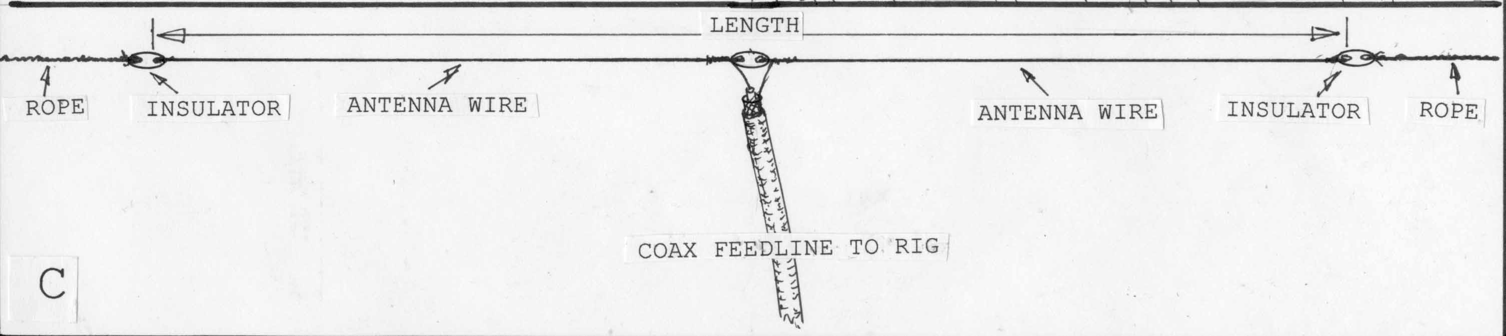
The
halfwave dipole antenna (fig. 1C) is found useful from the upper portion of the
MF band on into the microwave region. It is most common on HF where it is more
responsive to distant stations when strung a half wavelength above the ground,
and to closer-in stations when strung a quarter wavelength high. Never mount it
near power lines.
Cut
your elements by the formula given above, and solder them in place on the three
insulators as shown in Fig. 1C. An acceptable antenna-to-feedline match for HF
or lower frequency reception will usually be obtained using any good coaxial
cable for the feedline. Well discuss why this is so in more detail another
time.
Solder
the feedline to the antenna as shown, and insulate the exposed end of the coax
with coax sealant. Then run the feedline to your receiver. We wont worry
about using a balun for now, well talk about their function another time. But
dont forget lightning-induced damage protection: the minimum is to disconnect
and ground the antenna when it is not in use, and never use it when weather is
likely to produce lightning.
For
more on dipoles check out http://members.tripod.com/%7Ecb_antennas/antenna_basics.html.
And here is a short tutorial of antenna technology: http://www.gigaant.com/antennabasics/basicknowhow/
This
article first appeared in Monitoring Times, March 2002 "Antenna Topics"
|