|
Antenna Primer Part I:
Copyright
by
Clem Small KR6A
Introduction
This
is the first of three parts of a primer on antennas and their applications. If
you already have some ideas about what antennas are and how they work, this
primer may help you organize and clarify those ideas. If you havent yet been
introduced to antennas, then this primer will start you on your way to working
with, and even building, your own antennas.
What
is an Antenna?
An
antenna is a device which either transmits radio (electromagnetic) waves into
the space around it, or receives radio waves from that space. It is possible to
make a simple, working antenna from a simple piece of wire. On the other hand,
some antenna designs are very complex devices with multiple, precisely
dimensioned conductors which are spaced at precise distances from one another.
There is a large number of different antenna designs available, and the
selection and utilization of an appropriate design is an interesting and
exciting part of radio communications.
A
Bit of History
It
is interesting that when radio waves were first demonstrated convincingly to the
scientific world, some of the basic antenna designs we utilize today were
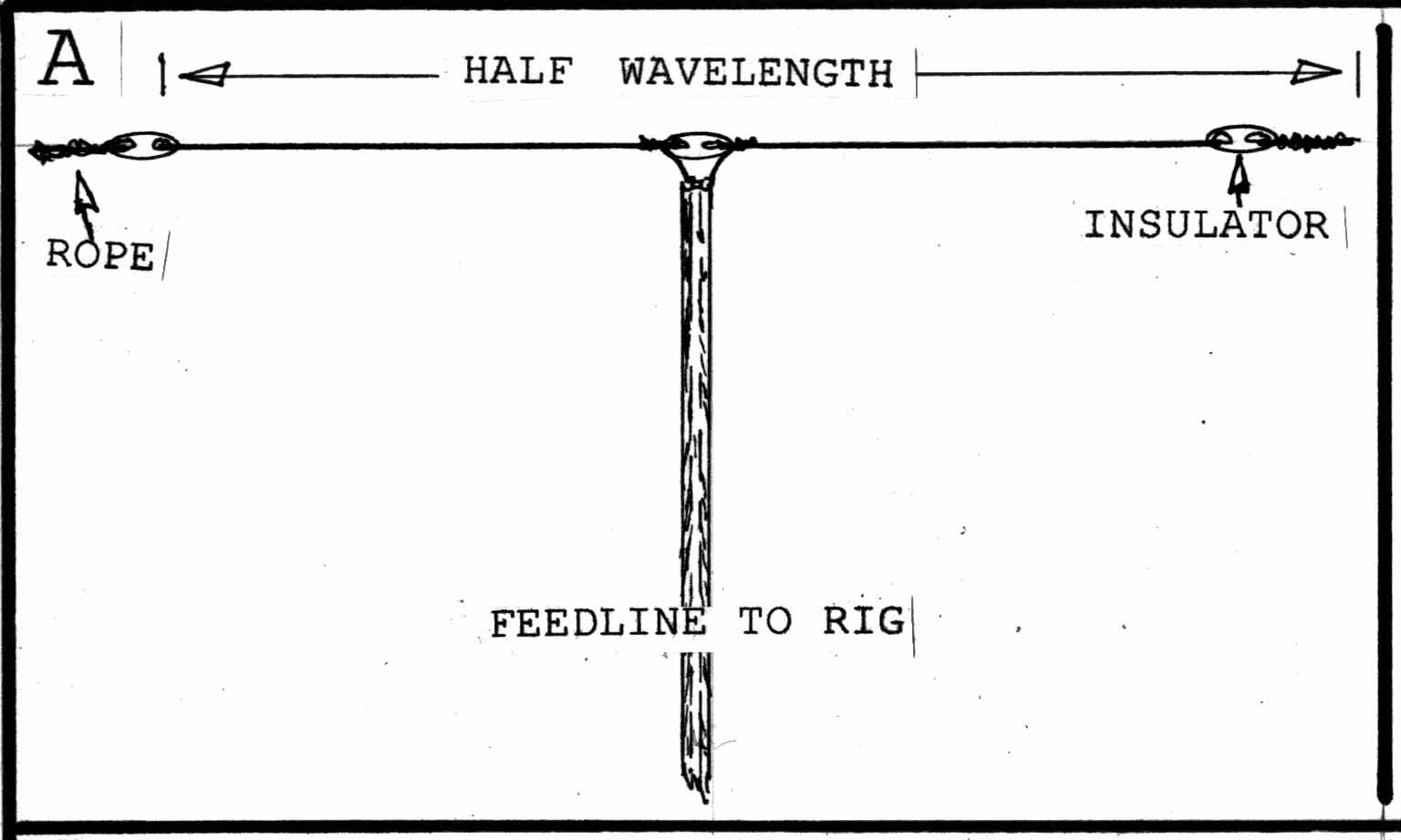
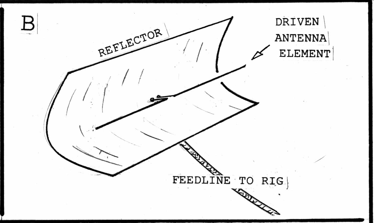
already developed. Henrik Hertz was the first scientist to convincingly show
that radio waves did in fact exist. And his early work reported such basic
antenna designs as the halfwave dipole, and the parabolic reflector antenna,
(figs. 1A, 1B). He also demonstrated the principle of the dielectric-lens
antenna.
Using
the discoveries of Hertz and others, Guglielmo Marconi developed a working radio
communication system. At one point in his work, Marconi took a Hertzian dipole
antenna and removed half of it. This left a quarter wavelength piece which
Marconi mounted upright on the ground. He left one feedline connected to the
bottom of the upright half of the dipole, and grounded the feedline connection
which had formerly been connected to the half which he had removed. The antenna
worked quite well, and in his honor it is called the Marconi, grounded,
quarterwave, vertical antenna. Today
it is utilized in many AM broadcast station installations and many shortwave
stations.
Marconi
and his engineers developed other antennas also, most notably the L-antenna and
the Imperial Beam. Whereas the Marconi grounded quarterwave antenna transmitted
and received equally well in all compass directions, the L and Imperial antennas
were directional antennas, or beams. This means that they could focus their transmitted energy or
reception responsiveness in particular directions.
In
addition, Marconis engineer Franklin developed a phase-based design for
antenna elements which causes an antenna to focus its waves somewhat
perpendicular to the antenna. Various versions of the Franklin design remain
quite useful today for both to-the-horizon coverage with very high frequencies
(VHF) and higher frequencies, and in beam antennas for high frequency (HF)
operation.
To
support the growing utilization of trans-oceanic radio communication, a number
of very large directional beam antennas were developed from circuits used in the
early days of radio. One class of these beams was derived from an antenna known
as a long wire antenna. These include the V-beam, and the rhombic beam,
and were known as wire beams. Curtain beams were gigantic beam
antennas with a large number of elements forming something like a hanging
curtain. They often utilized a second antenna behind the main antenna (driven
element) to reflect RF energy such that the beams radiation-pattern was
primarily unidirectional.
George
Brown discovered that beams could be improved by spacing their elements closer
than the quarter wavelength that had formerly been utilized between driven
element and reflector. Another important development was the Yagi-Uda beam
antenna, in which both a reflector and director element were used in addition to
the main (driven) element to give greater directivity and higher gain than was
previously available. The relatively small size of the Yagi-Uda beam meant that
at frequencies above 10 MHz one could have an antenna which was both highly
directive and able to be rotated by remote control. Remote control greatly
facilitated pointing the antenna for maximum performance in any compass
direction.
As
radio technology developed, operation became practical on higher and higher
frequencies. In the VHF, and particularly the UHF and microwave bands, the small
size of the wavelengths involved led to the development of many antenna designs
which would have been too large to be practical at lower frequencies with their
longer wavelengths. Antennas such as the helical, corner reflector, dish
reflector, waveguide, horn, slot and patch antennas are examples of designs more
practical at the shorter wavelengths. Many of these designs have been utilized
in radar, cross-country repeaters, and for space, satellite and aircraft
communications. Various reflector-type antennas have been important in the
development of radio astronomy.
Many
other types of antenna designs have been of considerable importance in the
development in various areas of radio communications. Wide band, multi-band and
the so-called frequency-independent antennas have facilitated ease of
switching between multiple frequencies. As early as the pioneering days of
wireless some radio direction-finding antenna designs were put to use for
general radio-location, location of enemy transmitters in wartime, and for
search and rescue operations at sea.
Some
of the areas where todays engineers are looking for new antenna designs, as
well as adapting existing designs, include space and satellite communication,
and putting antennas inside cell phones, pagers, and digital-computer
accessories such as wireless mice, and wireless modems.
And
So:
This
historical sketch is necessarily abbreviated, but it is easy to see that antenna
technology has a long and important list of contributions to the advancement of
radio technology. In the next installment well continue with a
discussion of some of the important concepts youll need to appropriately
select and utilize antennas for your own use. Well also talk about building
your own dipole antenna.
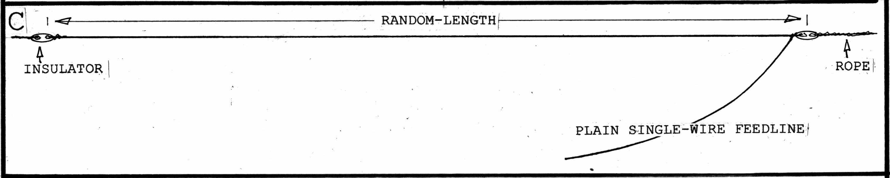
For
the beginner wanting an antenna to use for general monitoring on high frequency,
medium frequency, or even lower in frequency, one of the easiest to make is the random-length
wire antenna. Start by finding a good place to string the wire as high,
long, and in-the-clear as possible. Get enough metal wire of any kind and size
that is strong enough to hold together for the distance you intend to span. Put
the antenna up with insulators at each end as shown in fig. 1C, and run the end
into your radio room. Dont string it near power lines. Connect the end of the
antenna to your receivers antenna input terminal, and start monitoring.
Dont
forget lightning-induced damage protection: the minimum is to disconnect and
ground the antenna when it is not in use, and never use it when weather is
likely to produce lightning.
Here
is an interesting site with lots of tips for beginners: http://my.integritynet.com.au/purdic/antennas-rules.htm
This
article first appeared in Monitoring Times, February
2002 "Antenna Topics"
|